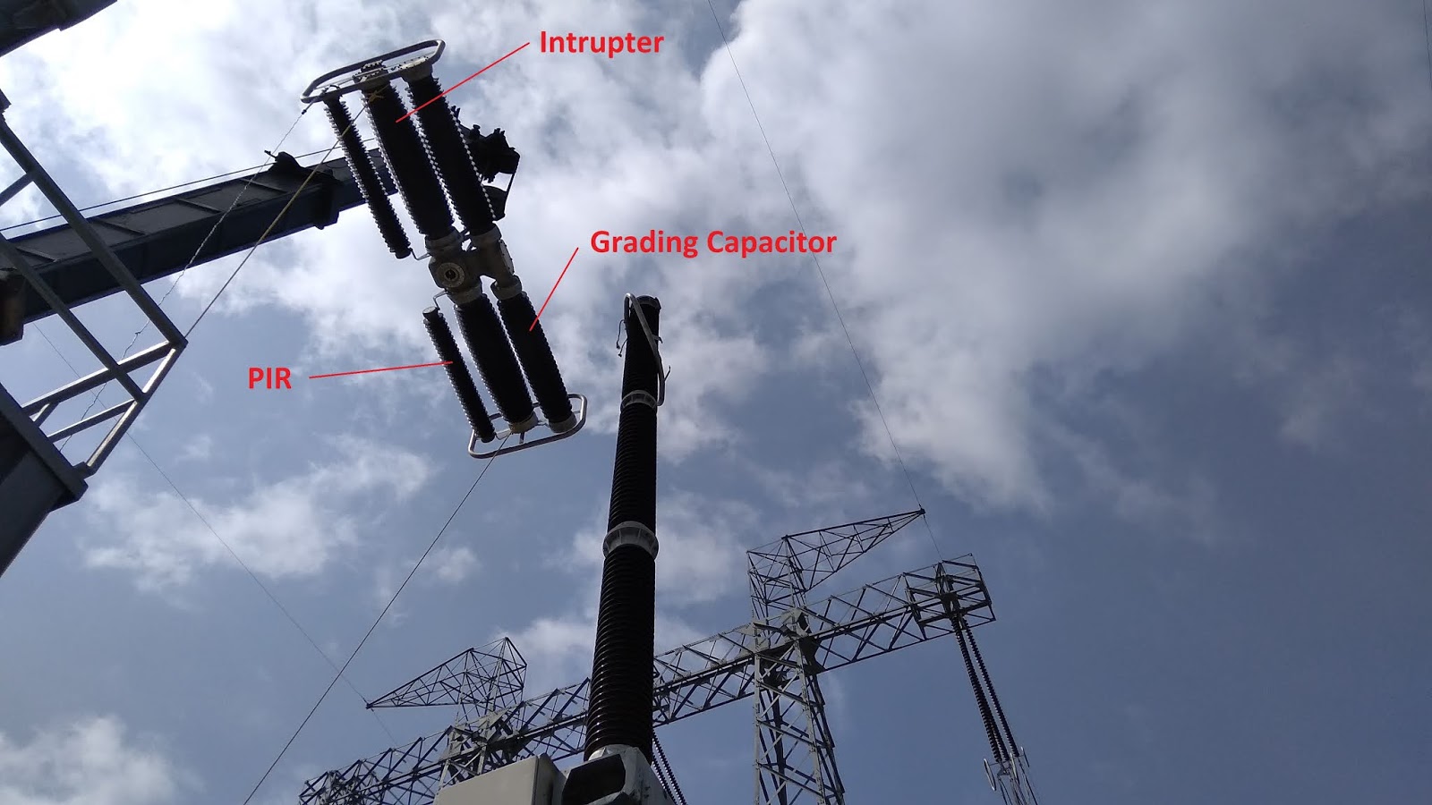
Pre-Insertion Resistor & Zero Missing Phenomenon
 |
| Inside of PIR |
Large generation of reactive power occurs in HVAC due to the capacitance of the long transmission lines and cables.
To compensate the
reactive power, shunt reactors are typically installed. Due to their inductive characteristics,
these can raise other technical challenges within the system.
The current in the inductor should maintain its continuity and when it is connected at a voltage
zero, the current will have a DC component with an amplitude equal to the amplitude of the AC component.
The duration of the DC component depends on the resistance of system components e.g. resistance of shunt reactor winding,
external grid, export cable and transformers.
If the inductor is
connected at a peak voltage, no DC component will be present because the
current will be zero at that moment.
The capacitive current
of the cable and transmission line are leads system voltage by 90 degrees, and inductive current of the shunt reactor lags by 90 degrees.
If energized at voltage
zero, both the inductive and capacitive currents are in phase opposition to
each other and tend to cancel out. This leaves a DC current in the incoming
breaker, with no zero crossing for a period of time.
During this period it
is not feasible to re-open the circuit breaker (e.g. if a fault in the cable
exists) because the circuit breaker should find the current zero for an arc
interruption. This can take a long time (sometimes seconds) to attain. Hence,
it is called zero missing phenomenon (ZMP).
There are different
mitigation methods addressed in the article for ZMP and the application of any particular the method depends on the system conditions like operating voltage, cable length
and location of the system.
Fig. 1 shows the
current for the cable or (transmission line) and shunt reactor in phase opposition. These two currents
cancel each other out, leaving the DC component.
The magnitude of the DC
component depends on the amount of compensation, where lower shunt compensation
results in a lower DC component. The ZMP can theoretically be avoided by limiting
the compensation to less than 50%.
However, this may
increase transient overvoltage, and cause the need for a larger STATCOM / SVC
for meeting grid code reactive capability requirements.
EFFECT OF SYSTEM PARAMETERS ON ZERO MISS DURATION:
The duration of ZMP
depends on various parameters of the system. It is important to determine the
maximum zero miss duration (ZMD) before implementing any mitigation methods.
A. Switching angle
The maximum ZMD is
observed when the circuit breaker is switched at voltage zero (simultaneous or
single pole). There is no ZMD observed for the circuit breaker when switched at
voltage peak (single pole).
B. Grid short circuit strength
The damping of the DC
component of the shunt reactor current during energization, and during faults, depends
upon positive and zero sequence impedance of the grid.
The resistance for
maximum fault level is less as compared to the minimum fault level, which therefore
leads to slower damping of the DC component
C. Degree of compensation
The maximum ZMD is at
100% compensation when the capacitive and inductive currents completely cancel
each other out and only the DC component remains.
Above 100% compensation, the inductive current is greater than capacitive current, and hence, only some AC
component remains, resulting in a reduction of the ZMD. There is no ZMD below 50%
compensation provided the shunt reactor has a minimum resistance to damp out
the DC component.
PRE-INSERTION RESISTOR:
Circuit breakers with
pre-insertion resistors (PIR) are often installed to damp out the transients
during energization. There are basically two different PIR configurations:
parallel and series PIR.
In parallel PIR configuration (Fig. 3a), the resistor
switch is in series with the resistor bank, and both are in parallel with the
circuit breaker interrupter, where the interrupter operation follows the PIR
switch operation.
In a series PIR configuration (fig. 3b), the resistor switch
is in series with the circuit breaker interrupter but in parallel with the
resistor bank.
The different characteristic quantities of a circuit breaker with closing
resistors as shown in Fig. 4
The closing time
interval is defined as time between energizing the closing circuit, the
circuit-breaker being in the open position, and the instant when the contacts
touch in all poles.
The make time
interval is the time between energizing the closing circuit, the
circuit-breaker being in the open position, and the instant when the current
begins to flow in the first pole.
Pre-arcing time
interval is the time between the initiation of current flow in the first pole
during a closing operation, and the instant when the contacts touch in all
poles for three-phase conditions, and the instant when the contacts touch in
the arcing pole for single-phase conditions.
For a parallel PIR,
PIT is defined as the interval of time during a closing operation in any one
pole between the instant of contact touch of resistor switch, and the instant
of contact touch in the main breaking unit of that pole.
For circuit breakers having
series connected PIR, the PIT is defined as the interval of time between the
instant of the last contact touch in any closing resistor element, and the
instant of the last contact touch in any main breaking unit.
From the above
definition, the PIT for both the configurations are different for different phases.
The PIT mentioned in this paper is the time for which the resistor in each pole
is in circuit before the contact touching of the main breaking unit of that
pole.
The standard also
specifies typical manufacturing tolerances for resistors to be considered. If a
manufacturer has been selected, they should state the value of these
tolerances.
In addition, they should state the range of PIR insertion times which
they can achieve (including time tolerances), as these are typically realized
mechanically, and therefore depend on the physical design and ambient
conditions.


Comments
Post a Comment